November 4, 2004: Closing the West Gap: Cables, Floor panels, the Gap
Today I had the opportunity to visit the junction between the west approach and the west platform - to see another movement in this symphony of bridge construction. Joining the approach to the platform does not "just happen", but requires adjustments of platform location, placing floor girders and panels, building cable bundles and adjusting their tension - all so that the edge girders are perfectly aligned for final splicing.
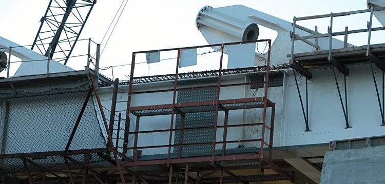
Here is the west ramp and
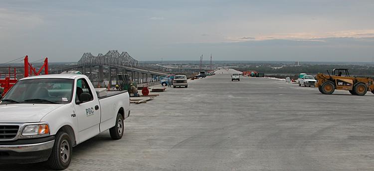
the west platform.
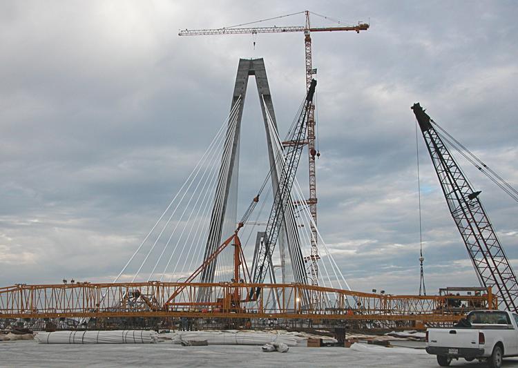
Joining the platform with the west approach requires first placing the north and south edge girders, erecting the floor girders, building the cable bundles in order to raise the platform as the strands are tensioned and placing the concrete road and walkway panels.
Here are shown the floor girders and the north anchor with its master strand initially tensioned to remove the slack in the white stay pipe. Freyssinet provides the engineering, materials, installation and testing of all aspects of the cable stays. Note in the lower left, the positions of the ends of the two edge girders. The platform edge girder actually moves up and down a couple of inches in response to platform movement - creating an interesting moving target. The floor girders here are sisters of the floor girders I saw at High Steel Structures last weekend.
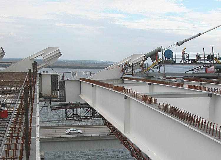
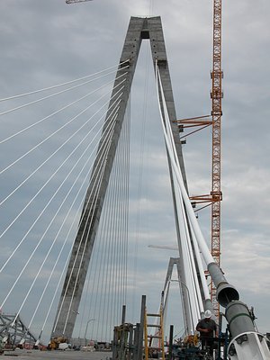
A view of the south anchor array (113) from the west approach. Note the slack in the cable pipe (supported by the master strand joining the anchor with the west pylon
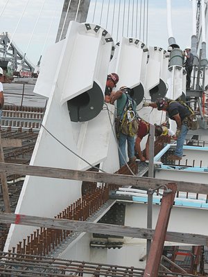
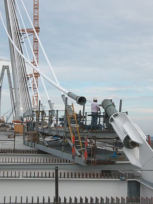
Here you can see the reduction in slack as the master strand is tensioned. Note the position of the polyethylene stay pipe in the left photo. The master strand (a single cable within the white stay pipe) is tensioned with a hydraulic jack by the guys at the top of the pylon (actually inside). You can see the reduction in slack as the cable is tensioned (right).
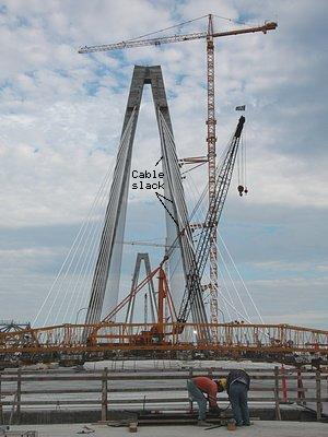
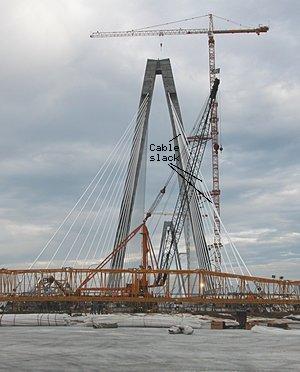
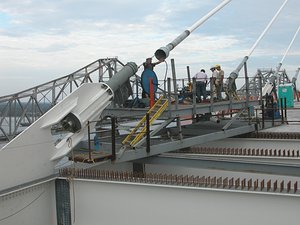
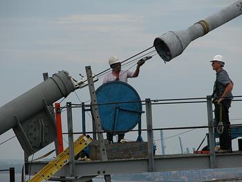
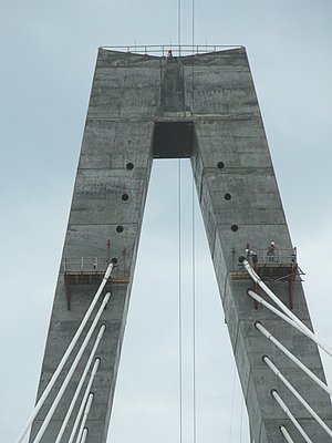
Erecting the cable pipes and assemblying the cables requires two teams, one on the platform (left) and one on the pylon face (right)
Here are views of the cable stay pipe as the master strand is being tensioned. Note the greater curve shown on the left compared with the right
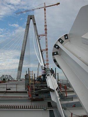
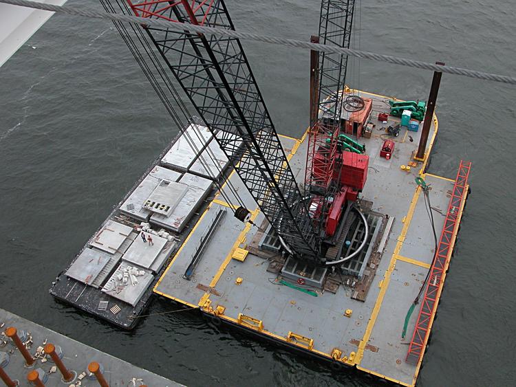
Floor panels on a barge - the smaller panels are for the (in my dreams) frank starmer pedestrian walkway and bike path. The large panels are for the roadway. Click on the image and you can see the numbers written on each roadway floor panel. Each panel has its special place on the platform.
Some video of picking up a pedestrian walkway floor panel from the barge and placing it on the edge girder supports (quicktime). Ignore the audio - the wind was blowing and sort of over powered my small camera.
- Lowering the cable (5 Mb)
- Raising the panel (16 Mb)
- Lowering the panel (16 Mb)
- Final placement (16 Mb)
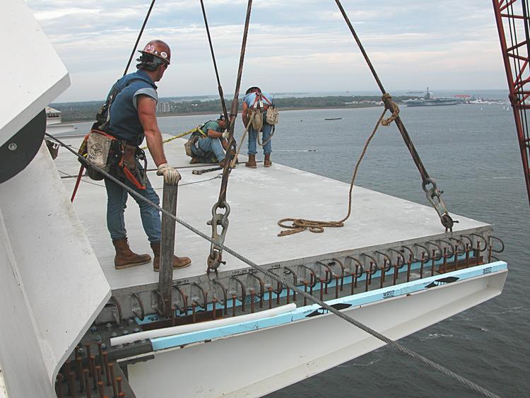
Placing the floor panels: Note the support girders extending perpendicular to the edge girders.
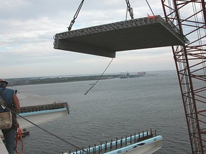
Final orientation
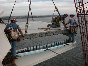
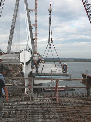
The final resting place
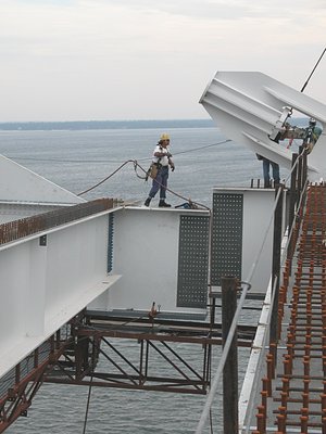
A gap walker
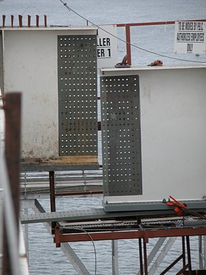
The north gap which varies about 2-3" vertically as the deck rocks If you look carefully, you can see the difference in alignment of the top to the right beam relative to the bolt holds: left, the top is below the row of holes, right, the top of the beam is aligned with the row of bolt holes.
So how are the two girders aligned so that they can be spliced together? David Wertz from the SC DOT has clued me in about the complexities of connecting the final anchor beams - joining first the west approach with the west deck and in about a month, the east approach with the east deck. David said:
"Interestingly enough, neither one of the girders will actually be connected to the approach span until possibly next week. As you probably noticed, the west end of the girder is hanging a couple of feet lower than the approach girder. In order to get everything lined up right, the rest of the steel on this segment will have to be placed, the net traveler will have to be rolled onto this segment, the entire west tower deck will have to be "unjacked" back toward the approach, the next pair of cables will have to be installed and partially tensioned, additional tensioning will have to be done to the previous pair of cables, deck counterweights will have to be moved, and deck panels will have to be placed. Then and only then will all of the bolt holes be lined up perfectly to do the final bolt-up at the connection to the approach."
"To add a little detail to the "unjacking" that was mentioned, last week, the entire 1/4 mile long west deck was jacked toward the channel about 3 1/2" using a few 200 ton hydraulic jacks to prepare for the placement of the last two edge girders. The deck will have to be slowly and partially released back to get the alignment just right for the final connection."
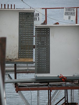
Nov 7, 2004
Closing the gap. Thursday (Nov 4) there was about a 2-3"
vertical misalignment. At that time, the 13th cable stay pipe was being erected.
Below you see the finished cable bundle, but incompletely tensioned as
evidenced by the slight downward bowing of the white cable pipe. The vertical
misalignment appears to be less than an inch (shown below).
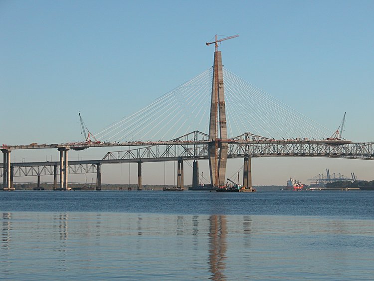
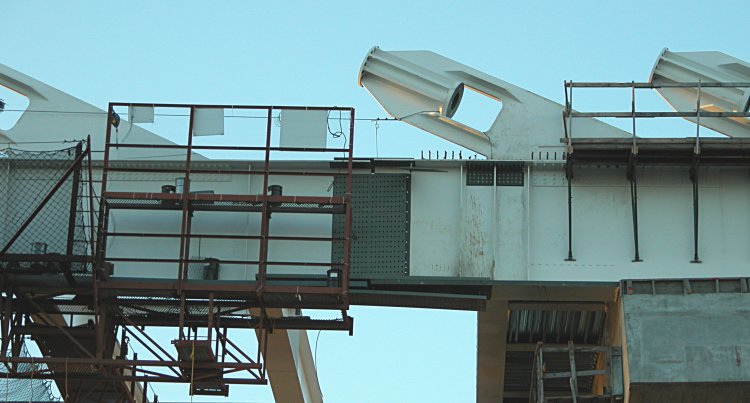
Here you can see the splice plate in position - horizontally misaligned by one vertical row of bolt holes and vertically misaligned by less than an inch. The cable tension will be increased to provide vertical alignment and the hydraulic jacks will push the platform to provide horizontal alignment.
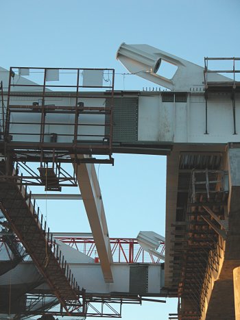
Compare the Nov 4 gap (left) with this morning's (right) gap (Nov 7). Note the light seen through the right vertical row of bolts that is not covered by the splice plate. The horizontal misalignment is about the width between two vertical columns of bolt holes.
November 14, 2004
Finished splicing the west approach to the west deck